The Engineer’s Compass: An Analytical Review of the SDE’s Ladder of Abstraction
Introduction: Charting the Modern Infrastructure Stack
The primary challenge for modern software and platform engineers is not a scarcity of tools, but the absence of a coherent mental model to navigate the dizzying layers of abstraction they represent. We work on platforms built on services, which run on infrastructure we rarely see. The user’s proposed “Ladder of Abstraction” provides an essential map for this complex terrain. This report serves as a rigorous, evidence-based validation and expansion of that model, offering an honest guide to the architectural layers software development engineers (SDEs) interact with daily.
This analysis will systematically deconstruct each layer of the ladder, integrating industry data, architectural principles, and real-world case studies to substantiate its core claims. Each layer of abstraction exists to decompose and manage a specific domain of complexity. A central theme of this report is the fundamental architectural divergence between the discrete execution model of tools like Terraform and the continuous reconciliation models at the heart of systems like Kubernetes. This divergence represents the most significant fault line in the modern stack, and understanding it is critical to making sound architectural decisions.
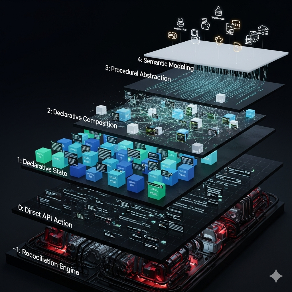
The framework for this analysis is the “Complete Ladder of Abstraction,” which provides the terminology and structure for the subsequent investigation.
| Layer | Name | Core Concept | How it Decomposes Abstraction | Key Abstraction |
|---|---|---|---|---|
| -1 | Reconciliation Engine | A stateful, continuous control loop that makes reality match a desired state. | Decomposes live system drift via controllers that observe and act until convergence. | The raw, imperative cloud APIs. |
| 0 | Direct API Action | You tell the system how to do something, step-by-step. | Decomposes the data center into discrete, consumable API endpoints, hiding the physical hardware and network fabric. | The physical hardware and network fabric. |
| 1 | Declarative State | You describe the desired end state of a single logical resource. | Decomposes a resource’s lifecycle into a single state definition, hiding the sequence of imperative API calls needed for creation or updates. | The imperative API calls for one resource. |
| 2 | Declarative Composition | You define a schema for a graph of related logical resources. | Decomposes an application stack into a graph of interconnected resources, hiding the complex dependency management and order of operations. | The dependency graph (DAG) and the persisted state boundary. |
| 3 | Procedural Abstraction | You use a programming language to generate a declarative composition. | Decomposes infrastructure patterns into reusable software components (classes, functions), hiding the verbose and logic-less declarative configuration. | The verbose declarative configuration (YAML/HCL). |
| 4 | Semantic Modeling | You model your infrastructure based on business concepts. | Decomposes infrastructure into business-centric services, hiding the underlying cloud primitives and implementation details entirely. | The infrastructure itself. |
Part I: The Foundational Layers of Infrastructure Interaction
Layer -1: The Reconciliation Engine — The Unseen Foundation
The engine room of the modern cloud is not a pristine, logically consistent foundation. It is a complex, stateful, and often inconsistent implementation of a cloud service’s internal machinery. This is Layer -1, the Reconciliation Engine. It comprises the continuously running controllers that form the Kubernetes control plane. Its core purpose is to continuously work to make reality match a desired state.
This layer’s function is to decompose the problem of “state convergence” via continuous control loops. Controllers observe the desired state (as stored in the API server/etcd) and the actual state of the world, then issue corrective actions until the two align. There is no discrete, idempotent interface or transaction boundary at this layer; idempotency lives at Layer 1 (resource semantics), while Layer -1 provides eventual convergence through repeated observe–compare–act cycles. Effects are realized through control-plane and node agents (e.g., kubelet, CNI, CSI, cloud-controller-manager) that perform imperative operations against runtimes and provider APIs. Cloud provider control planes similarly use internal agents and workflows to enact changes on underlying infrastructure; these implementations are intentionally opaque. Layer -1 orchestrates these effects and hides the immense complexity of distributed state management, error handling, and retries, presenting a unified control plane over otherwise disconnected services.
It is at this foundational layer that Kubernetes finds its true architectural home. Despite often being marketed as an application platform (PaaS), Kubernetes is often described as a “data center operating system”. Its core components—the API server acting as a central communication hub, the scheduler assigning workloads to nodes, and the controller manager running reconciliation loops—operate on a persistent, distributed key-value store called
etcd.1 This architecture perfectly matches the definition of a “stateful engine that works to make reality match a desired state”1
etcd reliably stores the configuration data, representing the desired state of the cluster at any given time, while the controllers continuously observe the actual state and issue commands to converge the two.1 Kubernetes, therefore, is not the platform itself, but the powerful, general-purpose reconciliation engine upon which platforms can be built.
Importantly, tools like Terraform Core and AWS CloudFormation do not live at Layer -1. They belong at Layer 2 (Declarative Composition): they take declarative inputs, compute an execution plan, and perform discrete, ordered operations against Layer 0 APIs. They do not continuously reconcile drift; once an apply/stack update finishes, the engine stops. Continuously running control planes—exemplified by Kubernetes controllers and many provider-internal service controllers (e.g., Auto Scaling Groups maintaining desired capacity, ECS Service scheduler keeping desired task counts, managed database failover)—fit the definition of Layer -1, though most provider implementations are opaque.
Layer 0: Direct API Action — The Imperative Baseline
At the most fundamental level of interaction with any cloud platform is the direct API action. This is Layer 0, where a single command results in a single, discrete action. It is the realm of imperative, step-by-step instructions: you tell the system precisely how to achieve a task. This layer abstracts the physical hardware—the servers, switches, and storage arrays in a data center—behind a consumable API, but it abstracts nothing more.2
Functionally, Layer 0 decomposes the physical data center into discrete, callable API endpoints. It takes a single command from a user or script as input (e.g., aws ec2 run-instances) and relies on the underlying physical and virtualized hardware to execute it. Its output is a single, stateless change to a resource.
While Layer 0 offers the ultimate degree of control and flexibility, it is inherently brittle and unscalable for managing complex systems. Each action is unaware of the broader context. There is no blueprint, no record of the desired end state, and no mechanism for detecting drift. Managing infrastructure at this layer is the digital equivalent of laying bricks by hand without an architectural plan—possible for small tasks but completely untenable for constructing a durable, repeatable system. It is the necessary but insufficient foundation upon which all higher-level abstractions are built.
Layer 1: Declarative State — The Illusion of Compression
The first great leap forward in infrastructure management was the shift from imperative commands to declarative state. At Layer 1, instead of telling the system how to create a resource, you describe the desired end state of a single logical component. This layer abstracts away the specific sequence of API calls needed to create or update that one resource. A Dockerfile or a single Kubernetes Deployment.yaml manifest are prime examples of this paradigm.
This layer’s primary function is to decompose the lifecycle of a single resource and provide idempotency. It takes a declarative manifest from a user or higher-level tool as input. It then relies on Layer 0 APIs to achieve the desired state. For example, when you apply a manifest, the Layer 1 logic first checks the current state of the resource. If the resource doesn’t exist, it issues a “create” command (a Layer 0 call). If it exists but is different, it issues an “update” command. If it already matches, it does nothing. This ensures that applying the same declaration multiple times always results in the same end state, hiding the procedural “if-then-else” logic from the user.3
However, the verbosity of common declarative formats, particularly YAML, often creates an illusion of abstraction rather than a genuine reduction in complexity. This analysis validates the critique that a typical Kubernetes manifest is little more than a text-based transcription of an API object’s fields. It describes the “what” for a single resource, but it provides no meaningful compression of intent. The amount of text an engineer must write is often directly proportional to the number of API fields they need to configure, which in turn is proportional to the number of imperative API calls they would have otherwise made.4
Part II: The Great Divergence: Discrete vs. Reconciling State Models
Layer 2: Declarative Composition — Infrastructure as a Graph Database
The dominant paradigm of modern Infrastructure as Code, pioneered by tools like Terraform and AWS CloudFormation, is found at Layer 2. This layer represents a monumental leap beyond the single-resource declarations of Layer 1 by introducing the concept of declarative composition. Here, you define a schema for an entire graph of related logical resources. The key abstraction it provides is not just the individual API calls, but the complex dependency graph and the order of operations required to safely create, update, or destroy an entire application stack.
The genius of this model is its architectural pattern: treating infrastructure not as a collection of items, but as a graph database. This analogy is technically precise.
- Graph Schema: The .tf or .yaml configuration files define the schema of the graph. resource blocks are the nodes in the graph. References between resources (implicit dependencies) and depends_on blocks are the edges that define relationships.5
- Graph Instance: The state file (.tfstate or a CloudFormation Stack object) is the persisted instance of this graph database. It maps the logical nodes and edges in your code to the real-world resources and their relationships in the cloud.6
- Graph Operations: A terraform plan is a query against this graph. Terraform builds a Directed Acyclic Graph (DAG) from your configuration, compares it to the state, and determines the correct traversal path (the order of operations) to create, update, or delete resources in parallel where possible.5 The terraform apply command then executes this traversal plan.
This model’s primary function is to decompose a complex application stack into a graph of interconnected resources, hiding the complex scheduling logic from the user.7 It takes a collection of declarative files as input and relies on the idempotent principles of Layer 1 for each node in the graph. Its output is a correctly sequenced series of Layer 0 API calls.
However, it is critical to understand that this process is not transactional in tools like Terraform. Unlike a database commit, a terraform apply operation is not atomic. If an error occurs midway through the execution, Terraform does not automatically roll back the changes. The operation halts, leaving the infrastructure in a partially applied state, which often requires manual intervention to reconcile. This stands in stark contrast to AWS CloudFormation, which is designed with a transactional model that attempts to automatically roll back to the last known stable state upon failure.
The Declarative/Runtime Divide — Blueprints vs Reality
A critical source of complexity in modern systems is the conflation of two distinct kinds of state:
- Declarative State (the blueprint): The intended baseline captured in files (YAML/HCL) and schemas. Examples: container image tag, resource limits, autoscaler policy (e.g.,
minReplicas,maxReplicas, target utilization). - Runtime State (the reality): The dynamic, continuously changing state produced by controllers in response to live conditions (Layer -1). Examples: the current number of pods (e.g., 7) due to an HPA reacting to traffic, leader elections, in-flight job counts.
The problem is that many APIs fail to clearly distinguish between the two. Allowing users to set spec.replicas in a Deployment while also enabling an HPA is a leaky abstraction: it invites declaring what is fundamentally a runtime-controlled value. The result is an ownership conflict and perpetual drift.
This creates a predictable failure mode:
- The declarative source (Git/Terraform) says
replicas: 3. - The runtime engine (HPA) scales to 7.
- A subsequent
kubectl applyorterraform apply“corrects” the drift back to 3, fighting the control loop and risking an incident.
The correct use of the ladder is to declare the behavior and invariants of the runtime (policy, bounds, targets), not to pin its transient state. Treat runtime values as observations, not configuration.
Practical guardrails and patterns
- Prefer policy over snapshots: configure autoscalers and controllers (bounds/targets), not their momentary outputs (replica counts, desired capacities).
- If an autoscaler is enabled, do not set its target’s instantaneous knobs. In Kubernetes, manage
HorizontalPodAutoscalerand omit or de-emphasizeDeployment.spec.replicasto avoid fights. - In cloud autoscaling (e.g., ASG), treat
desiredCapacityas runtime. Ownmin/maxand policy; let the controller decide the momentary value. - Use Kubernetes server-side apply with field ownership so human/CI and controllers own disjoint fields. Avoid multi-writer contention on the same field.
- Enforce ownership at the gate: admission policies and linters that reject PRs which set runtime-owned fields (e.g.,
replicaswhen HPA is present). - Provide safe operational overrides via short-lived, dynamic configs (feature flags/overrides with TTLs) rather than permanent Git commits. Ensure automatic expiry.
- Surface runtime via status, metrics, and events. Never make status an input to configuration.
Decision checklist: is this value declarative or runtime?
- Does a control loop change it autonomously? If yes, it’s runtime.
- Is it derived from live demand, health, or feedback? Runtime.
- Is it a bound/limit/policy that constrains behavior? Declarative.
- Are there multiple writers (human, CI, controller)? If yes, separate fields/ownership or redesign.
- Would “correcting” it during an incident likely fight the system? If yes, make it an override with TTL, not a baseline.
Concrete examples
- Kubernetes: prefer declaring HPA policy; treat
Deployment.spec.replicasas runtime when HPA exists. Baselines belong in HPA; live replica counts belong to the controller.8 - Jobs/CronJobs: completion counts and active pods are status, not configuration.
- Databases: storage class and backup policy are declarative; current replica lag, failover leadership, and connection counts are runtime.
The Declarative/Runtime Divide and the Kubernetes Anomaly
The central crisis in modern infrastructure management, and the primary source of friction when using tools like Terraform to manage Kubernetes, is the conflict between two types of state:
- Declarative State (The Blueprint): This is the state defined by engineers in files (
.yaml,.tf). It represents the intended baseline configuration. This is what Layers 1 through 4 are designed to manage. Examples: a containerimage, a memory limit, or the configuration of an autoscaler (minReplicas: 3,maxReplicas: 10). - Runtime State (The Reality): This is the dynamic, fluctuating state of the live system, managed by the Layer -1 engine in response to real-world conditions. In Kubernetes, this is the state managed by controllers in the control plane, which continuously work to make reality match the desired state stored in
etcd. A prime example is the current number of pods being 7 due to high traffic, as determined by a Horizontal Pod Autoscaler (HPA).
The problem is that the APIs we use often fail to distinguish between the two. The ability to set replicas: 3 in a Kubernetes Deployment.yaml is a leaky abstraction—a fundamental API design flaw. It invites the user to declare a value that is fundamentally a runtime concern.
This creates an irreconcilable conflict, particularly when a discrete execution tool like Terraform manages dynamic Kubernetes resources. The core problem is state drift:
- The Declarative State in Terraform’s state file says
replicas: 3. - The Runtime State managed by the HPA in Layer -1 says
replicas: 7.
On the next terraform plan, this discrepancy will be reported as “drift.” An unsuspecting operator might “correct” this drift by running terraform apply, which would instruct the Kubernetes API to scale the Deployment back down to 3, potentially causing an outage by fighting against the cluster’s own autoscaling mechanism.8 This is not a tooling problem; it’s an architectural impedance mismatch. The correct use of the declarative ladder is to define the behavior of the runtime (the HPA configuration), not to dictate its transient state (the current replica count).
This has led to the mainstream view that the “native” solution is GitOps, where tools like ArgoCD and Flux use a Git repository as the external source of truth.9 However, this view is an oversimplification. Logically, a Git repository in a GitOps workflow and a
.tfstate file in a Terraform workflow play a similar role: they are both external, declarative sources of truth that are reconciled against the cluster’s internal state in etcd.10 The true difference is not the existence of an external state, but the
reconciliation model:
- Terraform’s Model: A discrete, synchronous, push-based model. An external agent (a CI/CD pipeline) initiates a change by pushing it to the cluster via the API server. Reconciliation happens only when terraform apply is run.
- GitOps’ Model: A continuous, asynchronous, pull-based model. An in-cluster agent (the GitOps operator) continuously pulls the desired state from the Git repository and applies it. Reconciliation is always active.
Furthermore, the GitOps model is not without its own severe anti-patterns. A naive implementation can lead to a “configuration monolith,” which is fundamentally at odds with a microservice architecture.11 If all microservice configurations are stored in a single, large Git repository, that repository becomes a central point of contention and a deployment bottleneck. A change to a single service requires a pull request to this monolithic repository, coupling the release cycles of otherwise independent teams and violating the principle of independent deployability.11 This centralized model can also be a significant security risk; a compromise of the single ArgoCD instance managing all clusters could be catastrophic.12
Part III: Ascending the Ladder — Towards True Semantic Abstraction
Layer 3: Procedural Abstraction — Infrastructure as Software
Layer 3 marks the escape from the inherent limitations of purely declarative, domain-specific languages like HCL and YAML. It acknowledges that at a certain scale, infrastructure is a software problem that is best solved using software engineering principles. Tools at this layer, such as the AWS Cloud Development Kit (CDK), CDK for Terraform (CDKTF), CDK8s, and Pulumi, allow engineers to use general-purpose programming languages to generate the declarative compositions of Layer 2.
This layer’s function is to decompose infrastructure patterns into reusable software components. It takes high-level code (e.g., a Python class) as input and hides the verbose, repetitive, and logic-less nature of Layer 2 configurations. Its output is a fully-formed Layer 2 declarative composition (e.g., a CloudFormation template or a set of Terraform configurations), and it relies on Layer 2 tools to plan and apply this generated configuration.
However, as the user’s analysis correctly identifies, this layer is still tightly coupled to the underlying tools and their conceptual models. A comparison of the distinct architectural models of AWS CDK and Pulumi is instructive.
- AWS CDK: The Transpiler Model: The AWS CDK functions as a transpiler. The code written by an engineer does not directly provision infrastructure. Instead, when executed, it synthesizes AWS CloudFormation templates. These templates are then deployed by the CloudFormation service operating at Layer 2 (Declarative Composition), which performs a discrete, ordered stack update against Layer 0 APIs. Debugging can be challenging because errors often manifest in the generated template, not in the original CDK code.13
- Pulumi: The Direct Orchestration Model: Pulumi operates as a direct orchestration engine. The code written by the engineer is the deployment program. The Pulumi engine executes this code, making direct API calls to the cloud provider to provision resources. This model provides a tighter feedback loop and a more familiar debugging experience, but it is still a discrete executor (Layer 2 orchestration + Layer 0 calls), not a continuous Layer -1 reconciler.
Layer 4: Semantic Modeling — The Platform Engineering Endgame
This is the final rung of the ladder, the ultimate goal of modern platform engineering. Layer 4 is about building an internal platform that speaks the language of the business and its application architectures, not the language of infrastructure. The key abstraction at this layer is the infrastructure itself. Developers do not request a VM; they instantiate a new WebService({ team: ‘billing’ }).
Layer 4 decomposes infrastructure into business services. It takes a simple, high-level semantic request from a developer as its input and hides the entire underlying infrastructure stack. It relies on the layers below it to translate this business need into a pre-approved, compliant, and fully-configured set of resources. The primary vehicle for this is a well-designed Internal Developer Platform (IDP), which provides a curated, self-service experience through “golden paths”.
Crossplane is a prominent technology that aims to provide the engine for such platforms. It extends the Kubernetes API to manage external resources. A platform team can define a new Custom Resource Definition (CRD) like kind: ProductionPostgres. This is backed by a Composition, a blueprint that translates this abstract request into concrete cloud resources, relying on the Layer -1 Kubernetes reconciliation engine to do the work.14 However, this approach inherits all the operational burdens of its foundational layer, making it a difficult path that requires a high level of organizational maturity.
Part IV: A Critical Re-evaluation of the Kubernetes Ecosystem
The Kubernetes ecosystem, while powerful, is not architecturally pure. It contains design choices and complexities that merit a critical examination, as they are often the source of significant friction for engineering teams.
The Schizophrenic Tool: kubectl
The kubectl command-line interface, the primary tool for interacting with a Kubernetes cluster, exhibits a design that can be described as schizophrenic. It operates across multiple layers of the Ladder of Abstraction simultaneously, forcing operators into constant and confusing context-switching.
- Layer 0 (Direct API Action): Commands like kubectl run my-pod --image=nginx are purely imperative.
- Layers 1 & 2 (Declarative State & Composition): The command kubectl apply -f my-manifest.yaml is declarative.
This dual nature creates a dangerous workflow antipattern. An engineer might use the declarative kubectl apply to deploy an application. Later, during an incident, they might use an imperative command to quickly mitigate an issue. This directly modifies the live state of the cluster, but the declarative source of truth—the YAML file—remains unchanged. The live system has now drifted from its declared state.1
The “Piled Up” Design: Architectural Hacks and the kubectl exec Wormhole
The most compelling evidence that Kubernetes is not a coherent, top-down design but rather a pragmatic collection of features piled up over time is the existence of architectural “hacks” like kubectl exec. This command is a wormhole to a “-NaN” layer, a purely imperative escape hatch that completely bypasses the declarative, state-driven model that is the system’s core philosophy. While indispensable for real-world operations, this command is a philosophical contradiction. It acknowledges that the declarative abstraction is insufficient for the messy reality of debugging.15 It is a pragmatic solution added to solve a critical operational need, but it fundamentally breaks the abstraction layer.
The Reality of the Complexity Tax
The accumulation of pragmatic design choices, leaky abstractions, and operational necessities results in a significant “complexity tax.” This is not merely a steep learning curve; it is a continuous operational burden that shifts engineering resources away from application development and toward infrastructure management. Industry surveys consistently cite operational complexity and skills gaps as top challenges for Kubernetes adopters. This aligns with practitioner sentiment that day-to-day cluster work often skews toward operations-heavy tasks relative to engineering and incident response.
Gell‑Mann Amnesia and Leaky Abstractions in Practice
The Gell‑Mann Amnesia effect reminds us that trust in simplified narratives can be misplaced, especially when we personally know a domain’s messy details. Paired with the Law of Leaky Abstractions, it implies caution: simple APIs often sit atop complex, failure‑prone machinery. A practical example is ingress controllers: a Kubernetes Ingress object abstracts routing, yet historically crafted inputs (e.g., annotations) could influence generated lower‑layer configurations in unsafe ways. The lesson is architectural, not vendor‑specific: when an abstraction compiles user input into complex configurations, assume the lower layer’s threat model still applies.
The Lie of Portability: A Tether to the Cloud
One of the most persistent marketing claims about Kubernetes is that it provides true portability. This is a dangerous oversimplification. While the Kubernetes API for application-level objects is portable, any real-world, stateful application has dependencies on storage, networking, and identity that are fundamentally non-portable.16
- Storage: A PersistentVolumeClaim (PVC) is a portable request, but the StorageClass that fulfills it is backed by a cloud-specific Container Storage Interface (CSI) driver that provisions a non-portable volume like an AWS EBS volume or a GCP Persistent Disk.
- Networking: An Ingress object is portable, but the controller that implements it is tied to a specific, non-portable cloud load balancer.17
- Identity: Securely accessing cloud services requires non-portable mechanisms like IAM Roles for Service Accounts (IRSA) on AWS or Workload Identity on GKE.
In reality, Kubernetes provides API portability, not implementation portability. Migrating a complex application between clouds is not a simple matter of kubectl apply; it is a significant re-engineering effort.
Conclusion: The Inescapable Necessity of Abstraction
The central challenge of modern engineering is not solving the inherent complexity of business logic, but taming the accidental complexity of the tools used to implement it. The Ladder of Abstraction is not a menu of options; it is a map of this conflict. Attempting to leapfrog its layers—to solve a high-level problem with a low-level tool—is a direct path to an exponential, unmanageable increase in accidental complexity.
This “accidental complexity” is the technical debt incurred when an engineer is forced to manually re-implement the core function of a skipped abstraction layer. For example, when attempting to model a dynamic business process (a Layer 4 concern) directly with the static data templates of Layer 2, the engineer must invent a fragile, bespoke templating language within YAML or HCL. The complexity of this workaround—and its inevitable maintenance burden—grows exponentially as it tries to approximate the features of a true programming language, a problem Layer 3 already solves.
This pattern repeats at every level. Describing a multi-component application (a Layer 2 concern) with the isolated manifests of Layer 1 forces the creation of brittle external scripts to manage the dependency graph that Layer 2 tools handle natively. At the bottom, attempting any repeatable process with the fire-and-forget commands of Layer 0 requires building a custom, often flawed, state-management and idempotency engine from scratch. In each case, skipping a layer does not remove complexity; it forces the engineer to recreate that layer’s purpose in an ad-hoc, unsupported, and ultimately more complex manner.
The inescapable conclusion is this: abstraction is the only viable weapon against runaway complexity. Each layer exists precisely to solve the inherent limitations of the one below it. The goal is not to eliminate complexity—the business logic itself is complex—but to ensure that the complexity an engineer grapples with is proportional to the business function they are building, not the accidental, self-inflicted complexity of the underlying stack. To climb the ladder is to manage complexity; to skip its rungs is to be buried by it.
Common layer-skipping failure modes
- Managing Kubernetes Deployments via Terraform while HPA is active: the tools fight, causing oscillations or outages.
- Centralizing all microservice manifests into one GitOps repo: a configuration monolith that kills independent deployability.
- Treating runtime values (replicas, desiredCapacity) as declarative baselines: perpetual drift and incident-driven “corrections.”
- Mixing
kubectlimperative fixes with declarative Git: silent drift and surprise rollbacks in the next apply. - Modeling multi-component apps with only Layer 1 manifests: brittle hand-ordered deploys and dependency footguns.
- Automating with Layer 0 scripts: no idempotency, no state, high blast radius re-runs.
References
-
Kubernetes - Wikipedia, accessed September 3, 2025, https://en.wikipedia.org/wiki/Kubernetes ↩ ↩2 ↩3 ↩4
-
Infrastructure as code - Wikipedia, accessed September 3, 2025, https://en.wikipedia.org/wiki/Infrastructure_as_code ↩
-
GitOps: A Comprehensive Guide - DEV Community, accessed September 3, 2025, https://dev.to/iaadidev/gitops-a-comprehensive-guide-909 ↩
-
Role Of YAML In Infrastructure As Code - Meegle, accessed September 3, 2025, https://www.meegle.com/en_us/topics/infrastructure-as-code/role-of-yaml-in-infrastructure-as-code ↩
-
Dependency Graph Terraform - HashiCorp Developer, accessed September 3, 2025, https://developer.hashicorp.com/terraform/internals/graph -
State Terraform HashiCorp Developer, accessed September 3, 2025, https://developer.hashicorp.com/terraform/language/state/purpose -
WTH is Terraform Graphs?. Terraform Graphs by Aditya Dhopade Medium, accessed September 3, 2025, https://medium.com/@adityadhopade18/understanding-terraform-graphs-2c8742aa6021 -
Is Terraform for Kubernetes Applications Flawed? For Kubernetes, GitOps is The Way, accessed September 3, 2025, https://dev.to/sarony11/is-terraform-for-kubernetes-applications-flawed-the-case-for-a-gitops-native-future-49ce ↩ ↩2
-
A Paradigm Shift in Software Delivery: A Comparative Analysis of GitOps and Traditional CI/CD Uplatz Blog, accessed September 3, 2025, https://uplatz.com/blog/a-paradigm-shift-in-software-delivery-a-comparative-analysis-of-gitops-and-traditional-ci-cd/ -
How teams use GitLab and Terraform for infrastructure as code: A demo, accessed September 3, 2025, https://about.gitlab.com/topics/gitops/gitlab-enables-infrastructure-as-code/ ↩
-
Microservices vs. Monolith: 5 Key Differences - Codefresh, accessed September 3, 2025, https://codefresh.io/learn/microservices/microservices-vs-monolith-5-key-differences/ ↩ ↩2
-
Monolith splitting stories — Part 4 KISS the ArgoCD deployments …, accessed September 3, 2025, https://medium.com/@info_98249/monolith-splitting-stories-part-4-kiss-the-argocd-deployments-d94f4759584a ↩
-
Can someone who has used both Pulumi and AWS CDK describe the differences betwee… Hacker News, accessed September 3, 2025, https://news.ycombinator.com/item?id=26881542 -
Can Kubernetes Abstractions be Useful? : r/devops - Reddit, accessed September 3, 2025, https://www.reddit.com/r/devops/comments/j2g9s9/can_kubernetes_abstractions_be_useful/ ↩
-
Gell-Mann amnesia effect - Wikipedia, accessed September 3, 2025, https://en.wikipedia.org/wiki/Gell-Mann_amnesia_effect ↩
-
Terraform and GitOps: Automated Infrastructure as Code - Terrateam, accessed September 3, 2025, https://terrateam.io/blog/terraform-and-gitops ↩
-
Overview Kubernetes, accessed September 3, 2025, https://kubernetes.io/docs/concepts/overview/